In the field of biopharmaceuticals, how to ensure that the instruments and equipment not only meet the compliance requirements, but also realize the rapid mixing of powder and liquid solvents without agglomeration – this is an important issue in the product preparation and mixing process. The powder mixer is the core equipment to realize the mixing process. The powder mixer independently developed and produced by Bola Precision Machinery, through the optimized design of the gap between the stator and the rotor and the combination of the two-stage impeller structure, relies on the high-speed rotation of the rotor to achieve material suction. And dispersion mixing, so as to ensure that the mixing is uniform and thorough, and the process requirements are realized.
Part 1 Background
In recent years, with the rapid development of domestic biopharmaceutical, medical cosmetology and other industries, and the continuous upgrading of production technology, the equipment of the preparation system has also accelerated technological innovation. In the preparation and production mixing process stage, the traditional stirring and mixing method can basically achieve a good solid-liquid mixing effect, so that the solid particles can be wetted or dissolved quickly. However, in the process of processing some special materials, the effect of traditional stirring and mixing is not ideal. Even after increasing the mixing time, there are still a series of problems to be solved: such as insufficient mixing of powder agglomeration, powder feeding During the process, positive pressure conveying is used to generate dust and so on. At this time, only the traditional processing method-stirring and mixing with a stirring device often cannot guarantee the consistency of product quality between production batches.
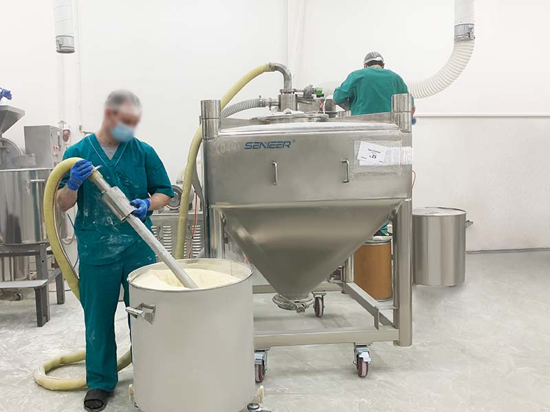
At present, the rotating equipment used in this process section mainly includes stirring system, disperser and powder mixer. Among them, the powder mixer is more suitable for the mixed production of large-scale products because of its small footprint, high continuous production efficiency, and good mixing effect on material powder. This paper takes the Burla powder mixer MF200S as an example, and analyzes and introduces it from the operating principle of the stand-alone equipment, the optimization of the body design structure, and the operation process of the mixing small unit system with the equipment as the core.
Part 2 Operating Principle Of Powder Mixer
The powder mixer equipment uses the motor as the driving unit, and drives the main shaft rotor to rotate at high speed through the flat belt transmission structure. Under the action of gravity, the liquid enters the diversion structure inside the mixer cavity through the liquid inlet; the internal rotor rotates at high speed to generate strong centrifugal force, and the liquid is discharged out of the mixer from the outlet. At the same time, under the action of centrifugal force and flow guide structure, the liquid forms a vortex above the rotor, forming a negative pressure zone, so that the powder can be sucked into the central cavity through the cavity pipeline above the rotor. While in contact with the liquid, the powder passes through the stator structure under the action of the centrifugal force of the first-stage impeller, and quickly dissolves with the liquid, thereby achieving efficient dispersion and homogeneity of powder and liquid. The last two-stage impeller will convey the material out. Due to the special design of the second-stage impeller, this mixer can not only meet the basic working conditions, but also realize high-proportion water-powder mixing and high-viscosity delivery. The fast and fully dust-free powder suction ability is realized through the reasonable design of the first-stage guide wheel; while the instant dispersion, full mixing, and high-viscosity delivery of materials rely on the joint action of the first-stage impeller and the second-stage impeller to achieve.
The key structure of the powder mixer is the primary guide wheel, the secondary mixing impeller and the chamber isolation mechanical seal. In order to increase the centripetal force of the first-stage guide wheel, it can be realized by increasing the radius of rotation and the rotation speed of the equipment rotor; in order to improve the relative movement between the two-stage mixing impeller structures, achieve instant extrusion mixing efficiency, and reduce the gap between the stator and the rotor And increasing the rotation speed of the equipment are two effective means.
Regarding the structure of the first-stage guide wheel, combined with the mechanical structure and the principles of fluid mechanics, it can be approximately understood as a device that converts kinetic energy into pressure energy by a mechanism that rotates at high speed to generate kinetic energy (1). When designing the first-stage guide wheel impeller, the following important parameters need to be paid attention to: flow channel curve, inlet aperture, fluid cutting angle, power consumption, etc. According to the second law of thermodynamics, in the process of converting kinetic energy into pressure energy, there is energy loss, and most of the lost energy is dissipated in the form of heat energy. As a result, in industries such as medical cosmetology and pharmaceuticals where materials are sensitive to temperature, the first-stage guide wheel will not only cause energy loss, but may also cause denaturation of the mixed material. Therefore, rationally designing the flow path curve, that is, the angular shape of the impeller blades, is an effective way to effectively reduce energy loss.
Ev=Ep+∆E (1)
Ev——motor output energy;
Ep——pressure energy, that is, effective energy;
∆E——thermal energy, that is, lost energy.
The mechanism formed by the stator and the first-stage guide wheel of the rotor can be understood as similar to the form of the volute and guide wheel of the centrifugal pump, so it can be simplified to the volute design. The design of its curved structure can effectively reduce the power consumption and heat caused by the resistance in the flow channel while improving the hydraulic performance of the impeller. In terms of theoretical calculation, without considering the influence of friction pipe resistance power consumption, the powder flow rate flowing through the flow channel can be calculated according to the following formula (2):
Q=2πR1B1V1=2πR2B2V2 (2)
Among them, B1 and B2 are the height of the impeller at the point where the relevant liquid flows through. Since the liquid needs to be accelerated to generate pressure, the height at the center of the impeller is higher than the height of the blade at the edge of the impeller, that is, B1>B2. R1 and R2 are the radii of any point in the flow channel, so R2>R1, V1 and V2 are the partial velocities on the circumference of the liquid flow corresponding to the radii R1 and R2, so V2>V1. It can be deduced from the above formula that when the rotational speed is the same, the circumferential component velocity V increases with the increase of the radius R. When the flow rate of the outer circle is large enough, because the rotating liquid forms a water ring seal, a strong negative force is formed at the central vortex. The higher the rotation speed, the greater the negative pressure; under the action of negative pressure, the powder is continuously replenished, and together with the liquid, it is transported outward along the center of the rotor to the stator and rotor for mixing.
When optimizing the relevant parameters of the guide wheel, it is necessary to comprehensively consider the flow channel curve (to reduce pipe resistance), the number of flow channels (output pressure), and the height of the flow channel. Another key parameter is the diameter of the impeller. The larger the diameter is at the same speed, the higher the linear speed of the impeller edge. , The mechanical properties are also put to the test. Therefore, when designing the first-stage impeller, we assisted the design with 3D software and adjusted the correlation size with the help of drawing software. Under the condition that the total output flow rate within the target demand range remains unchanged (that is, the output capacity and powder suction capacity are satisfied Bottom), through flow simulation analysis, it is finally confirmed that appropriately reducing the diameter of the impeller is the optimal choice to effectively reduce the temperature rise of the equipment and enhance the working stability of the equipment. The power consumption is mainly caused by the flow resistance of the flow channel formed by the rotation of the impeller. Therefore, in combination with the Good Manufacturing Practice (GMP), we adopt a five-axis machining center instead of the welding method in the guide wheel processing technology, and process the guide wheel at one time to ensure the consistency of the curved surface; through the surface of the impeller and the inner surface of the stator Mechanical polishing and electrolysis once to ensure that the surface roughness can be controlled below 0.4 μm, so as to reduce the friction of the fluid on the impeller.
During the rotation of the stator and rotor of the mixed structure of the two-stage impeller, the 30 sets of tile-shaped teeth uniformly arranged in the axial direction of the rotor and the tile-shaped teeth in the axial direction of the stator form a grid, which cuts and squeezes the material flowing through the gap between the two, so that The material is quickly and uniformly refined, and the radial clearance of the stator and rotor tile-shaped teeth is 0.5 mm. Near the center and the edge of the rotor, there are 5 uniformly distributed thrust blades and 20 uniformly distributed outer row impellers at an oblique angle, which ensure that the inhaled material passes through the designed flow path and achieves the purpose of full mixing.
Regarding the sealing structure of the model, in order to effectively isolate the working chamber of the MF200S mixer from the outside world, a combined structure of double mechanical seals is adopted. Since the equipment is a high-speed rotating equipment, the mechanical seal needs to use cooling sealing fluid. When the equipment is running, the coolant enters the gap between the moving ring and the static ring to form a lubricating film. At the same time, the cooling liquid in the flowing state can quickly take the heat away from the mechanical seal chamber, so as to avoid the friction of the moving and static rings of the mechanical seal, heat generation and burning of the mechanical seal. . In order to avoid the pressure generated when the MF200S mixer is sterilized in place (SIP) in the working chamber from pushing away the mechanical seal, the pressure of the mechanical seal is designed to be 2.5 bar.
Part 3 Process Flow And Test Of Mixed Unit System
3.1 Process Flow
The mixing unit system is mainly composed of the following equipment and components: a MF200S continuous mixer, a liquid mixing tank, a powder tank installed above the mixer, and a set of circulating pipelines connected to each other. The mixing unit system with MF200S as the core will use the continuous circulation method to evenly add the solid that needs to be mixed with the liquid into the liquid material.
The mixed solid material is put into the powder tank through the weighing system, the MF200S mixer is started, the valve of the feeding pipeline is opened, the high-speed rotating rotor of the mixer drives the first-stage guide wheel, a vacuum is formed in the center, and the powder is quickly sucked in; At the same time, the liquid phase is pumped and transported into the mixer, and the two are fully mixed together instantly under the action of the secondary mixing impeller. In order to prevent the mixed material from settling after entering the mixing tank through the material pipeline, according to the different viscosity of the material, a stirring device can be added at the bottom of the mixing tank so that the mixed material is always in a state of motion in the mixing tank, so that the mixed material The uniformity of the material can maintain a high degree of stability, reducing the difficulty of subsequent processing due to the inconsistency of the uniformity and concentration of the material. According to the process requirements, if the materials to be mixed pass through the MF200S mixer for many times, a circulation pipeline can be added to the pipeline of this system, so that the materials can be combined with the process requirements to complete multiple cycles and mixing. Adding a sampling valve or a detection device to the unit system can achieve the expected mixing effect after the material is confirmed by comparison, and then the mixed material in the mixing tank is pumped out through the centrifugal action of the secondary mixing impeller.
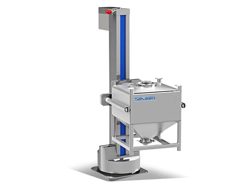
3.2 Mixing Test
The performance of the mixing system was tested, the material tested was carbomer powder, the filling liquid was ionized purified water, and the temperature was 15°C. An experimental mixing unit was used for testing. In the initial stage, considering that the powder enters the second mixing impeller earlier than the liquid through the vacuum action of the first stage impeller, the material may not be mixed or agglomerated, so liquid pumping is adopted. Fill the MF200S mixer with liquid first, and open the powder inlet valve at the upper end of the MF200S after the system receives the feed signal to allow the powder to enter.
Part 4 Test Results And Summary
Through the actual test of the mixing unit, it was found that 100 l of solvent was used to dissolve 3.5 kg of powder, and the resulting viscosity of the finished product was 106 389 mpas, which proves that the design achieves sufficient mixing of powder and can meet the needs of users.
With the continuous deepening and development of the field of biopharmaceuticals, the functions of the powder mixing system also need to be continuously improved according to the needs of customers, and the process automation process also needs to be further accelerated. Combined with the actual feedback from the customer’s field test, the direction for further optimization of the system is as follows:
(1) With regard to the control system, if the mixing system is used in pilot tests and production, it may be considered to use the formula scheme to input the control system in advance, and the manual adjustment links such as valves, sampling, and recording adjustments can be completed by the automated system with one key. Due to the higher degree of automation, the complexity of the system will also increase the types of system failures, which puts forward higher requirements for the control feedback system, and also puts forward higher requirements for the system maintenance personnel.
(2) In terms of the main body of the core equipment, the disassembly and assembly of the core equipment MF200S, especially the mechanical seal, needs to be equipped with a fool-proof device to ensure the consistency of the installation.
(3) In terms of system, if the CIP/SIP function needs to be configured, the tank body needs to consider the design of the pressure vessel and be equipped with a piping system for the inflow and discharge of cleaning fluid.


