Companies should focus on “the value of CIP cleanability design” – improving the cleaning performance of aseptic process components. This article will provide a fresh perspective for CFOs and those making capital expenditure decisions while also concerned with enterprise facility utilization, operating costs, and carbon emissions.
It is an indisputable fact that even in some new biological product production facilities, the cleaning process of pipes and vessels (valves and other components) still retains many manual or semi-automatic cleaning processes – probably because these processes have not yet been designed to facilitate CIP cleaning workflows. Since these manual or semi-automatic cleaning processes rely too much on human operations to varying degrees, they are unreliable and extend the effective production period of hours or even days, which invisibly has a negative impact on production capacity, production efficiency and even profit margins.
Take a large biologics company in South Korea as an example. The CDMO company has currently installed 96 000 gal (1 gal = 3.785 l) bioreactors and plans to install an additional 68 000 gal in the next two years. When the company changes products, it replaces all seals and diaphragms used in the previous production batch, and manually cleans all valves and other components, each change taking about a week. In other words, if the product needs to be changed frequently, more than 20% of the effective capacity will be lost. Though other equipment has managed to validate the CIP cleaning process during commissioning (often done in a hurry, not effectively improved upon, and still has numerous design flaws that can lead to “cleanability” issues), if the design of the system, vessel (tank, reactor, fermenter), valve and other components does not meet the requirements of “CIP friendly”, only 2 to 3 additional conditions that meet the TACT elements can be added to complete the cleaning verification.
TACT is:
- Time;
- Action, including parameters such as turbulence of the CIP fluid in the process line, flowing down the vessel wall;
- Chemistry (chemistry or concentration);
- Temperature.
Clean Design Urgently Needs Planning
The TACT method alone is not sufficient to produce a truly robust cleaning process without prior design for CIP cleanability. As we all know, the process of supplementing and improving parameters and re-validation is time-consuming and labor-intensive. Even if the cleaning validation of this process is completed, avoiding extremely long cleaning cycles (several days in a single run), the extensive use of high temperature and aggressive chemical additives will also cause serious damage to seals and valve diaphragms throughout the system. While the additional cost of water, energy, and chemicals in the process is huge, this cost is trivial compared to the lost capacity. Damage to seals and diaphragms not only creates a potential risk of contamination or cross-contamination (as shown in Figure 1), but also increases preventative maintenance costs.
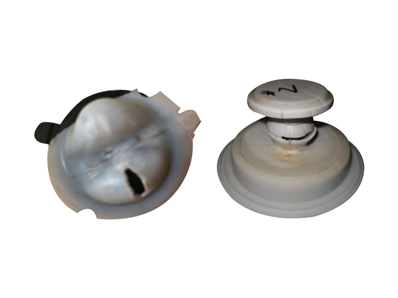
Figure 1 Left: Interlayer liquid accumulation in a ruptured PTFE/EPDM diaphragm in a double weir diaphragm; Right: Plunger diaphragm with compatibility issues with CIP additives
6 Challenges of Clean Design and How to Deal with Them
Learn from several articles based on scientific and risk-based approaches by authorities in the relevant fields: Reliable processes can significantly reduce risk, improve product quality, reduce verification pressure and simplify the verification process.
The following six major pain points are the key issues currently hindering the industry from realizing a fast and reliable CIP process.
-
Clean dead spots
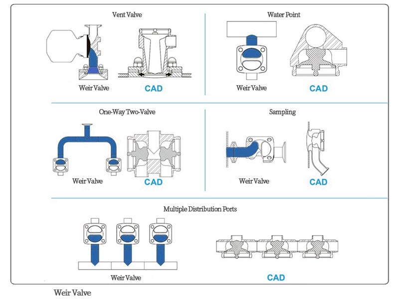
The ASME BPE (2019) standard requires L/d<2, and the prerequisite for this requirement is the use of weir valves on vertical pipelines (as shown in Figure 2). There is a blind end of length L between the valve seat and the horizontal main line (the “T” type is not recommended for weir valves); if a plunger valve is used, the diaphragm can be flush with the inner wall of the container and the inner wall of the pipe, so that L=0. Therefore, the use of a plunger valve (that is, to achieve L/d=0) can ensure that the branch in the vertical direction is easier to clean, and avoid biofilm formation in areas with low flow rates.
-
Asymptotic zones associated with O-rings, weir diaphragms, rupture discs, etc.
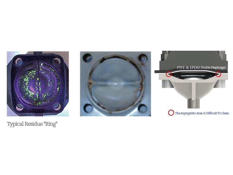
The turbulent flow created during CIP cleaning cannot reach the asymptotic zones associated with O-rings, weir valve diaphragms, rupture discs, etc., and they never drain. Due to capillary action, the interlayer between them, and between them and the metal, is filled with liquid, which is not evaporated until the system heats up – leaving a typical “ring” of residue (shown in Figure 3), which can be found during cleaning or maintenance.
-
Poor drainage of components
Due to their design, many valves do not drain easily. These valves are often recommended to be installed at an angle to “improve” drainage. Operators should follow this recommendation without replacing valves with better drainage designs. Traditional combination or block valves (usually weir valves) have more complex drainage situations and should be avoided. Plunger valves, on the other hand, have simpler drain lines for easy drainage.
-
Poor line drainage
When the drainage of the line is poor, an appropriate inclination angle can be applied to the pipeline. There are process lines available for gravity drainage in the ASME BPE (2019) standard.
-
Excessive total pipe volume
Valves with many different port options can be designed without dead space using 3D and P&ID design software, making them an excellent drainage solution by enclosing welds to specific functional areas. The designed valve can reduce the retention volume of the horizontal pipeline by 30% to 40%.
-
The maximum design flow of the tank bottom valve is less than the maximum CIP flow
If the maximum design flow rate of the tank bottom valve is less than the maximum CIP flow rate, there are usually 3 options: one is to choose a valve with a higher Cv; the other is to pressurize the vessel during the CIP process; the third is to apply a vacuum to the valve outlet during the CIP process. Of these, the third option is particularly useful for vessels that have been integrity tested using vacuum or to accelerate SIP processes (vacuum/steam pulses purge air and SIP condensate in the heating stage, and cool/dry in the cooling stage).
The Shirokizawa matrix is attached for reference [1] (as shown in Figure 4). The vertical axis represents the capability or reliability of the cleaning process (the smaller the number, the stronger the capability), and the horizontal axis represents the toxicity or risk level.
Summary
The pharmaceutical industry, especially the biopharmaceutical industry, is growing at an astonishing rate. The industry’s focus tends to be on the production process (like infusion), and some NNVA (necessary non-value added) processes (like cleaning or sterilization), don’t seem to have made progress over the past three or four decades. However, optimizing these NNVA processes can significantly improve business profits and productivity—especially for companies that are open to change.
【Reference】
[1] Andrew Walsh, Osamu Shirokizawa.The Shirokizawa Matrix: Determining The Level Of Effort, Formality, & Documentation In Cleaning Validation. Bioprocess Online, 2019.


