Key Points Of This Chapter
Lists 11 common problems in the granulation process: poor particle size distribution; formation of lumps or larger particles after the process; uneven distribution of poorly soluble API (active pharmaceutical ingredients); reduced API content; poor process air temperature control at low process air volume settings; bed stall; low yield; filter pressure drop continuously shows high readings; particles are too coarse during granulation; excessive loss; poor fluidization; and analyzes the causes of the problems and how to adjust them.
Lists 6 common problems in the drying process: incomplete transfer of materials from the high shear wet granulator to the fluidized bed processor in the complete system; wet materials transferred from the high shear wet granulator are not fluidized in the fluidized bed; drying time is too long; particles will fall apart after drying, with too much fine powder; final moisture content is inconsistent; and analyzes the causes of the problems and how to adjust them.
Three common problems in the coating process are listed: nozzle blockage; in the Wurster multi-nozzle coating process, the pipe of one of the nozzles will be subject to back pressure; the pump liquid pipe swings violently during the spraying process; and the causes of the problems are analyzed, as well as how to adjust these problems.
01 Granulation Process Problems And Treatment
Problem 1: Poor Particle Size Distribution (Acceptable Fine Particles Mixed With Wet Coarse Particles).
Possible Cause: Spray Gun Performance.
Solution:
Before processing any batch, perform a functional test on the nozzle to ensure that it is working properly. Poor particle size control and uneven moisture distribution are the most common problems among nozzle defects. An effective nozzle cleaning/maintenance and testing program is essential. After a major cleaning, the nozzle must be functionally checked at the expected spray rate and atomization pressure/volume. Replacing the nozzle (nozzle and air cap assembly) between batches is usually sufficient as a small cleaning to ensure proper performance, but sometimes poor particle size distribution occurs. The cause of this phenomenon may be an abnormality of the “O” ring and seal located in the nozzle tube. If this component is normal between batches, it is unlikely that the spray gun will have an abnormality in subsequent batches.
Problem 2: Formation of lumps or larger particles after the process ends.
Possible cause: Particle agglomeration-transition to a spherical shape and growth into larger particles.
Solution:
(1) Usually in the later stages of the spray process, there is a transition to spherical growth. Spherical growth indicates that there are a considerable number of very large agglomerates composed of particles, rather than the starting material. The solution to the problem depends on identifying the origin of the problem. The particle size growth process is from powder to nucleus to uniform agglomerates. As the particle size increases, the total surface area in contact with the spray liquid becomes smaller. At this stage, the solid phase velocity and density both decrease, and the material near the nozzle tends to be over-wet. Excessive surface moisture causes the particles to agglomerate and eventually form spheres. Although this situation is not common, it is undesirable and should be avoided as much as possible. This problem can be solved by increasing the fluidizing air volume or slightly reducing the spray rate.
(2) Because the generated “spheres” contain porous agglomerates, they can be effectively dried. However, their size affects the evaporation rate of water. The evaporation rate of large agglomerates is slow, and most of them will be distributed at the bottom of the bed. Therefore, they cannot be collected through the sampling port. The offline moisture of the final sampling test does not include the moisture content of the large particles at the bottom of the bed. After the granulation process is completed, samples are taken at different locations and ground for moisture testing. It is found that the final moisture content is higher than the moisture content at the end of the drying process (ps. This phenomenon occurs because the material taken by the sampling port is the material that falls from a high place in the normal fluidization, and the material that is “boiling” on the bed screen surface cannot be taken. In order to solve this problem well, either more sampling ports are added or online moisture detection is performed. The moisture measurement technology in PAT water has been introduced in the previous chapter and will not be repeated here).
Problem 3: Uneven Distribution Of Poorly Soluble API (Active Pharmaceutical Ingredient).
Possible cause: The Particle Size Of The API And The Excipient Is Incompatible.
Solution:
(1) The root cause of the unevenness must be found. Particle size analysis should be performed and the various components of the granules (generally up to 6 sieve levels) can be analyzed. The reason is usually a particle size incompatibility between the API and the granulation excipients, which is considered super-potency in one or more sieve components. At the end of drying and milling, a relatively rigid particle structure is definitely present. The COA of the API should have a particle size distribution, but no description of its shape. Needle-shaped structures may be problematic because the particle size distribution (using sieving methods) is a two-dimensional test of a three-dimensional material. SEM will reveal the shape and size distribution of the particles. If the API is found to be the root cause, additional steps need to be taken to make it compatible with the excipients (such as grinding), or the supplier must be asked to reduce the specification.
(2) If the API particle size is very small, but the material is sticky, small clumps of API may remain in the finished granulation. Compared to high shear wet granulation, the mechanical stresses in the fluidized bed process are much less. If the API is added as a dry feed to other excipients in the product container, it is recommended that it be co-processed (e.g., sifted, crushed, ground, etc.) with one of the excipients before being added to the other excipients. The shear during the co-processing process will be sufficient to eliminate lumps and get the mixing process off to a good start.
- At the end of the top spray granulation process, it is common practice to shake the fine powder that has passed through the capture bag into the product container. If this layer is an important material and contains very fine material, the content should be determined. If the material is found to be a highly active compound, the filtration system must be checked. In an alternating vibration type processor, the sealing airbag may have lost its ability to fully seal and must be repaired. As a result, there is still airflow during the vibration process, so the fine powder cannot be shaken out of the capture bag. On the surface, the filtration pressure difference is maintained at a relatively high level from the beginning to the end of the process. In a filter rod filter system, the effect is similar – when the fluidizing air continues to pass through the filter rod, the material adhering to the filter rod cannot be back-flushed off by the compressed air pulse and can only be released when the batch is finished and the fluidization stops. If this is a problem during process development and scale-up, it can be alleviated by trying different types of filter materials regardless of the filter vibration type (ps. Good quality and high-performance capture bags are a key factor in granulation, which needs to be paid attention to and investigated in the early stage of research and development. If necessary, please contact the capture bag supplier at the end of the article).
Problem 4: API Content Is Reduced.
Possible Causes:
(1) Poor Initial Distribution Of API;
(2) API Segregation;
(3) API Adheres To Machine Surfaces (Expansion Chamber, Outlet Air Filter);
Solution:
(1) Any suspected residue remaining in the bed should be analyzed for content and particle size to determine whether it is primary size or wet agglomerate. If the material is fine and dry, it is possible that segregation has occurred due to electrostatic charge. This may occur during the vacuum feeding stage or during the high temperature preheating stage 1-2 minutes before spraying. In both cases, the fluidizing air is dry and the environment becomes fertile soil for electrostatic charge. If there is a considerable residue and it is active, the process can be adjusted to strengthen fluidization so that the granular material enters the upstream of the expansion chamber and the outlet air filter to “wash” the residue off these surfaces (in the middle and late stages of spraying).
(2) There is no standard test to determine the porosity (ability to intercept particles) or permeability (air flow per unit time at a given pressure) of the capture bag or filter, but the performance of the capture bag or filter is very important. If the filter pressure difference is low, there is a risk of reduced yield. If the API particle size is small, it may also escape, resulting in low content. If this is the case, another type of filter material should also be tested – the filter material should not limit the process conditions, but should be selected to serve the product and process (ps. Good quality and high performance capture bag is a key factor in granulation, which needs to be paid attention to and investigated in the early stage of R&D. If necessary, please contact the capture bag supplier at the end of the article).
Problem 5: Process Air Temperature Control Is Poor At Low Process Air Volume Settings.
Possible Cause: The Machine Operating Temperature And The Qualified Lower Limit Of Airflow Are Too Close.
Solution:
It is a bad phenomenon when the process starts at low air volume and temperature, because the accuracy of the air flow sensor will decrease at low air flow, and the ability of the air handler to control low temperature at low air flow is also an extreme challenge and should be avoided as much as possible. It is recommended to use a higher air volume, even if this results in material being captured in the outlet air filter. If the filtration system is functioning properly, these fines will periodically fall from the bag or backflush, exposed to the spray liquid, and eventually become granules, as evidenced by the steady reduction in filter pressure drop during the spray process.
Problem 6: Bed Stall (In The Product Container Area).
Possible Cause: High Moisture Content During The Process And Late In The Spray Process.
Solution:
Experiments conducted to determine the operating range (design space) should determine the process moisture profile that reaches the failure limit. If this is done and moisture is tested during the process, then bed stall will be considered as a consequence of breaking this moisture “threshold”. A common reason for a sudden change from success to failure in daily production is an abnormal process air volume sensor. Many fluid bed top spray granulations, especially those with insoluble raw materials, are sprayed under conditions where the air leaving the bed is saturated with moisture and the liquid spray rate slightly exceeds the drying capacity of the process air. Therefore, the bed will generate moisture. Routine (quarterly or semi-annual) machine calibration includes the process air volume sensor (of all the instruments on a fluid bed processor, this is the most difficult to calibrate). Some companies perform a spot check, calibrating the instrument and its inverter while disconnected, others employ a loop check, where a test instrument is installed in series with the sensor connected in the loop, or a second instrument is used in the duct work to independently confirm the accuracy of the machine’s indicated values.
In both cases, if a change is made to the sensor, the processor user may not see any effect on the readings. For example, suppose the calibration finds that the air volume sensor indicates a reading 5% higher than it actually is (ps. indicates that the actual air volume is running 5% lower). When it is corrected, it may be found that the moisture content of the process and end spray of the first batch of processing is higher than usually seen. All process parameters are the same as usual, but the batch results are different. The problem is the air volume sensor. If the process is operated at saturation, the inlet and product temperatures will not change – they represent the conditions per cubic meter or cubic foot of air entering and leaving (saturation). A sensor found to be off by 5% means that less water is evaporated per unit time; therefore, the bed is hydrated faster. If the moisture buildup is rapid enough to reach the particle growth or bed stall threshold, the batch is in jeopardy. It is strongly recommended that all calibration data be discussed with the equipment user, especially any instrument changes involved, so that the impact of these types of problems can be anticipated and not “surprised”.
Problem 7: Low Yield.
Possible Causes:
(1) Wrong exhaust filter porosity;
(2) Coarse screen openings in the air distributor;
(3) Holes in the catch bag;
(4) Too long without bag agitation (or filter rod backflush).
Solution:
(1) Ensure that the API particle size is larger than the filter fineness of the catch bag or filter rod.
(2) If material appears in the bottom static pressure chamber, the loss may be due to material passing through the air distributor and may not be visible until the lower loader is removed.
(3) Damage to the capture bag may result in a significant loss of material. If this occurs, there may be a significant reduction in the capture bag pressure drop value. If you install a bag break detector (which should be required) and install appropriate sensitivity calibration downstream of the exhaust pipe, if the capture bag is damaged, the bag break detector will provide a signal to shut down the machine.
(4) The capture bag may be damaged after multiple cleanings. During installation, the capture bag may shrink and peel. Therefore, the capture bag should be checked for damage after each cleaning, before installation and during installation.
(5) After checking the integrity of the filter unit and completing the acceptance, if the filter unit is not tightly installed around the filter frame, you may find that the product flips over the seal during fluidization and eventually falls outside the filter unit. It will not be discovered until the filter unit is lowered at the end of the process. Therefore, ensuring that the capture bag is tightly installed around the filter frame can eliminate this problem.
- At the end of the process, due to static electricity, the material will stick to the wall of the expansion chamber.
Problem 8: The Filter Pressure Drop Continues To Show High Readings.
Possible Causes:
(1) The filter is clogged;
(2) The sensor measuring the filter pressure drop is clogged;
Solution:
There are three sensors used to measure the pressure drop (Δp): one below the material container in the lower aeration chamber, one in the expansion chamber, and the third above the filter. If the filter is clean and the filter’s Δp still shows a high reading, the pressure sensor tube above the filter is clogged with material because the sensor is exposed to any material that may pass through the filter. When the processor is cleaned, any material in the pipe, along with the water, essentially clogs the pipe and shows a high Δp value. Make sure that after each processor clean, all sensors, especially the filter Δp sensor, are thoroughly cleaned before the filter is placed in the equipment.
Problem 9: The Granules Are Too Coarse During Granulation.
Possible causes:
(1) Inlet air temperature is too low;
(2) The spray rate is too high due to improper pump calibration;
(3) The nozzle position is too low;
(4) The atomizing air is not turned on and the adhesive is not atomized;
(5) The nozzle is leaking;
Solution:
(1) Depending on the solvent used, increase the inlet air temperature to increase the product temperature.
(2) Ensure that the heating source (boiler, etc.) is working properly.
(3) Ensure that the nozzle is positioned so that the atomized droplets are evenly covered on the bed.
(4) The atomizing air pressure may be too low. Increase the atomizing pressure.
(5) The viscosity of the solution may be too high to produce finer droplets. You can dilute it before spraying.
(6) If the nozzle leaks, unstable fluidization will be obvious and the product temperature will continue to drop, depending on the position of the temperature probe.
(7) Reduce the spray rate.
(8) Ensure that the inlet volume is calibrated at regular intervals. The usual practice is to calibrate the pump with adhesive solution before spraying.
Problem 10: Excessive Loss.
Possible Reasons:
(1) The air inlet temperature is too high;
(2) The adhesive spraying rate is too low;
(3) Insufficient adhesive dosage;
(4) High fluidization velocity or air flow rate;
(5) The spraying volume reaches the nozzle limit;
(6) The adhesive is not suitable;
Solution:
(1) Reduce the air inlet temperature.
(2) Optimize the spraying rate.
(3) If the batch size is large enough, consider using a multi-nozzle nozzle.
(4) Reduce the fluidization air volume or use an alternating air distributor to reduce the air velocity.
(5) Increase the amount of adhesive or select an adhesive with higher mechanical strength after drying.
Problem 11: Poor Fluidization.
Possible Causes:
(1) Too much material;
(2) Incorrect distributor;
(3) Exhaust fan does not provide sufficient pressure drop;
(4) Air distributor is not cleaned thoroughly;
(5) The filter device has too small a filtration accuracy;
(6) Exhaust filter is clogged;
Solution:
(1) Reconsider batch and load.
(2) Ensure the use of a higher speed air distributor (tighter airflow).
(3) Evaluate exhaust fan capacity specifications, adjust material load or replace with a higher capacity exhaust fan, and revalidate the system.
(4) Ensure that the cleaning SOP has clear written provisions requiring the air distributor to be cleaned and inspected before installing the equipment.
(5) The filter device may have too large a restriction on the particle size of the material, and it may be necessary to find the appropriate porosity to intercept the material, but ensure sufficient air permeability. As mentioned above, the “experimental batch” can answer the suitability of the filter device.
(6) Check the filter pressure drop and adjust the filter shaking frequency and duration.
02 Drying Process Problems And Treatment
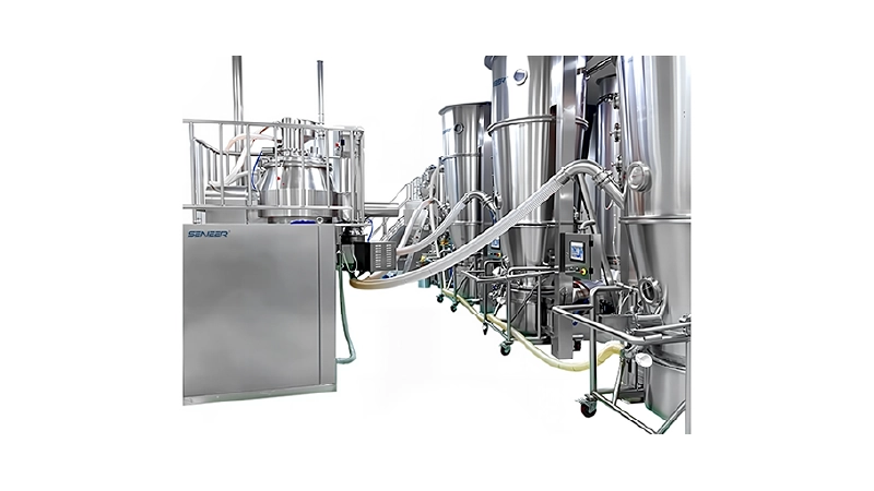
Problem 1: In an integrated system, the transfer of materials from the high shear wet granulator to the fluidized bed processor is not complete.
Possible Reasons:
(1) The fluidized bed does not have enough negative pressure to suck the material out of the discharge port.
(2) The Conveying Pipeline Is Too Long, With Too Many Bends Or Elbows.
Solution:
(1) Adjust the fluidizing air to generate enough negative pressure so that the material can be transported in the fluidized bed. According to the installation of the integrated system, when the material passes through the online granulation from the discharge port of the high shear wet granulator, there is a breathing valve in the pipeline. Even after adjusting the fluidizing air volume, if the product does not move and remains in the pipeline, by opening the breathing valve, the wet material in the pipeline gets additional air vibration to make it move.
(2) Minimize the distance between the fluidized bed and the high shear wet granulator.
Problem 2: The wet material transferred from the high shear wet granulator is not fluidized in the fluidized bed.
Possible Reasons: The Wet Material Is Too Strong Or The Fluidizing Air Velocity Is Insufficient.
Solutions:
(1) Passing the wet material through a granulator (conical mill) will help break up larger lumps and help dry more efficiently.
(2) Increase air volume to avoid filter plugging (monitor filter pressure drop).
(3) Transfer the wet material to the loading pot in small amounts at a time while the fluidized bed is running at very low air volume.
(4) Consider an integrated system that will connect directly from the high shear wet granulator to the fluidized bed for controlled feeding.
(5) Consider a tighter air distributor to increase air velocity.
(6) A mechanical rake may be required at the bottom of the product container to break up large, sticky wet lumps. There is enough time for mechanical action to break up any agglomerated lumps before the fluidizing air takes over.
Problem 3: Drying Time Is Too Long.
Possible causes: Temperature and airflow are too low, and inlet air humidity is too high.
Solutions:
(1) Increase the inlet air velocity to effectively suspend more material in the airflow.
(2) Increase the inlet air temperature (depending on the material properties).
(3) Provide a dehumidification system to reduce the dew point.
Problem 4: Raw Material Transcrystallization Or Crystallization
Solution: Consider drying at a lower temperature.
See the following two examples where low temperature helps prevent transcrystallization:
(1) Crystal form conversion during wet granulation has been reported in the literature. Wong and Mitchell found that chlorpromazine hydrochloride converted from form II to form I through an intermediate hydrate phase during wet granulation of an ethanol:water (80.5:22.9 v/v) mixture. The combination of granulation solvent and drying conditions provided a suitable environment for conversion to the alternate crystalline form.
(2) Davis et al. dried glycine granules at different rates. The drying rate determines the content of the polymorph. The faster the granulation is dried, the faster the supersaturation relative to the metastable form increases, and the greater the thermodynamic driving force for nucleation and crystallization of the metastable form. This can be demonstrated by the significant difference in polymorph content under different drying conditions. Granules dried quickly using fluidized bed drying have more crystals than granules dried using trays. In addition, the faster the fluidized bed granules are dried, the more a-glycine crystals will be produced. Using near-infrared technology, processing conditions such as drying speed can be adjusted to avoid potential polycrystalline transformation.
Problem 5: Granules Fall Apart After Drying And There Is Too Much Fine Powder.
Possible causes:
(1) Excessive airflow;
(2) Improper use of binder (quality and quantity);
(3) High temperature;
Solution:
During fluidized bed processing, intense mixing and particle-particle collisions and particle-container wall collisions occur. Particle breakage and abrasion during drying reduce the particle size of the product when it is dried, produce fine powder, and affect the flowability of the dried product. During the process development stage, the performance of the binder may be sufficient because of the smaller batch size and the effect of fluidization may not be obvious, but as the process scales up, the strength of the solid bridges between particles should withstand the intense fluidization. Fine powder formed by friction or abrasion is an important parameter in practice because it affects the flow characteristics of the granule quality. This breakage depends on the strength of the granules formed, which in turn reflects the type and amount of binder used in the granulation process. Generally, reducing the fluidization velocity during the drying stage will help reduce the generation of fines. Pellets can exhibit an inherent tendency to break during the drying process, depending on the moisture content, the type of binder, and the degree of stress exposed to the granules.
Problem 6: Inconsistent Final Moisture Content.
Possible causes:
(1) Inadequate process development drying curve;
(2) Improper fluidization;
(3) Uncalibrated temperature probe;
Solution:
(1) Measuring the moisture content of the material during the drying stage is critical. Many older units do not have a material temperature probe and rely instead on an exhaust temperature probe. Even if a material temperature probe is available, it and the exhaust probe calibration must be checked regularly (at a frequency of 6 or 12 months).
(2) Improper fluidization may be due to the air distributor becoming blocked at various locations. This can occur if the cleaning of the air distributor is not performed correctly and residues of previous product are left behind before a new batch is started. Proper cleaning SOPs and inspections are required to avoid this situation.
(3) During development, it is a good practice to establish a drying curve by taking samples at various stages of the drying process and correlating the change in humidity with the exhaust temperature. This will help you move the process through production and provide a way to determine the end of the drying step.
- In this case, implementing an online humidity sensor (such as a near-infrared probe) may be helpful.
03 Coating Process Problems And Solutions
Problem 1: Nozzle blockage.
Possible causes:
(1) Suspended particles in the pipeline are blocked.
(2) “Fish-eye white spots” appear in the aqueous dispersion polymer.
(3) If methacrylic acid polymer dispersion is sprayed, the fluidization temperature may be too high.
Solution:
(1) This problem is most common when spraying drug suspensions, whose particle size is much larger than the nozzle aperture. Before making the suspension, it is recommended to ensure that the insoluble components in the suspension are micronized.
(2) If the polymer is not affected by grinding, the prepared suspension can be ground by a homogenizer, or the insoluble components, such as talc, can be ground separately and then added to the rest of the coating solution.
(3) Reduce the distance between the nozzle and the pump station to minimize the possibility of particles settling in the pipeline.
(4) After any process interruption, the pipeline should be drained to avoid any settled particles from entering the nozzle, and ensure that the nozzle is large enough compared to the suspended particles.
Problem 2: During The Wurster Multi-Nozzle Coating Process, The Pipe Of One Of The Nozzles Is Subject To Back Pressure.
Possible cause: The nozzle is clogged.
Solution:
(1) The spraying must be stopped and the nozzle removed. In a multi-nozzle Wurster unit, a clogged nozzle can be easily identified by the pipe pressure (if the individual nozzles are equipped with separate pumps). The nozzle coating liquid may also be clogged because the material is at the nozzle mouth and has clogged the nozzle. If the product must be discharged from the loading pot due to a clogged nozzle (this is the case with most older equipment) and if the machine is equipped with an atomizing air volume sensor, before pausing the process, write down the volume (total nozzles or individual nozzles), discharge the material and repair the defective nozzle. After completion, test the nozzle under no load at the required atomizing air pressure (simulation test, if applicable). If the volume is equal to the value recorded before pausing, clear the nozzle annulus – reload the material and continue to finish.
(2) In some newer machines, the nozzle enters from the side of the loading pot, not from the bottom (this is why you have to empty the loading pot every time a nozzle is clogged). Since the nozzle is inserted from the side, the material does not have to be emptied and the nozzle can be quickly removed; the blockage can be cleared, the nozzle cleaned, and the nozzle mouth reinserted after the spray test. All of these activities can occur in a very short time while the fluidization is still running.
Problem 3: The Pump Liquid Pipe Swings Violently During The Spray Process.
Possible cause: There is a compressed air leak in the liquid line.
Solution:
(1) If the pump liquid pipe shakes erratically, this is a sign that compressed air is leaking into the liquid pipeline. This will cause a noticeable distortion of the spray pattern during particle coating or drug coating. If the machine is equipped with a mass flow meter, installed between the pump head and the nozzle rod, the display will jump (a good nozzle should produce a variation of only ±2-3g/min). Irregular pulses exceeding this value are an ominous sign and if discovered early in the batch, the process should be interrupted and the nozzle defect corrected, which can be prevented by functionally testing each nozzle before using it for the process.
(2) For transparent liquid pipelines, bubbles sometimes appear in the solution delivery pipeline. In addition to producing unstable shaking motion, it may also produce erroneous readings of the spray volume. Tightening the pipeline joints can eliminate bubbles and ensure that the liquid inlet pipe is completely immersed in the solution tank. Sometimes, foamy liquids can also cause similar problems; therefore, the foam formed during the solution preparation process must be removed by gently mixing to eliminate the air in the solution before starting to spray.

04 Summary
Process problem elimination depends on the collected data. The type of data and collection interval vary from supplier to user, but the first choice is to read the process data as much and as frequently as possible. For fluidized bed processors, at least all temperatures (dew point, inlet, material and exhaust), process air volume, atomization pressure and volume, and spray rate are included. Dependent variables should also include the pressure difference between the collection material and the outlet filter, and the liquid line pressure. In systems with complex air handling units, total air volume, preheater temperature, ambient air dew point, and dehumidification dew point can be added to the list. This recorded information is valuable in finding the root cause of the problem.
A control system that prints out all process parameters can identify any problems by studying these printouts. Properly trained employees will eliminate many process-related problems. At the same time, the development of the process must use experimental design to determine the critical process parameters. During the development phase, these parameters should be adjusted appropriately to avoid surprises during production. To be able to meet these process challenges, understanding the equipment and its functions as well as training and experience are prerequisites.


